หน้าแรก > งานบริการ > รับทดสอบการรับน้ำหนักเสาเข็ม Dynamic Load test
Procedure Dynamic Load test
introduction
Dynamic Testing is a powerful tool to assess pile capacity and movement relationships, driving stress, hammer performance, pile integrity and establish a driving criteria. The test can be applied for all type of pile such as pre-cast concrete pile, bored pile, timber pile and steel pile.
Dynamic Load Test is performed by measuring stress wave and move down the pile under impact of a falling. The reflected stress wave returns to the top due to soil resistance and changing of pile properties. The pile strain and acceleration are recorded by strain gauge and accelerometer near the pile top.
Dynamic Load Test can divvied into
-
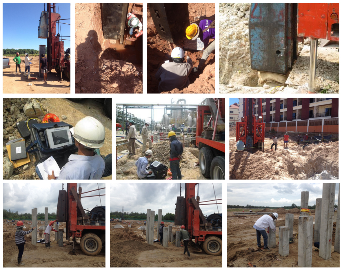
Initial Driving Test : is performed during the installation process. The testing purpose is for determine pile founding level, inspecting hammer performance, pile integrity, driving stress (compression and tension) at various drop height including pile capacity during driving.
-
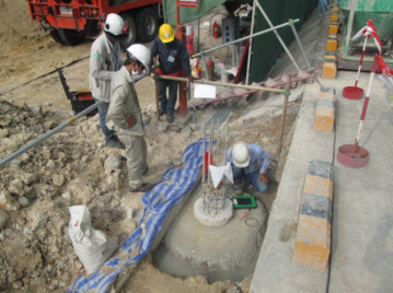
Re-strike Drive Test : is performed after pile installation. The test purpose is to determine pile bearing capacity as loading requirements. The pile capacity is usually increase with time due to soil setup
in shaft friction. The soil setup period is varied according to soil property.
Testing Equipments
-
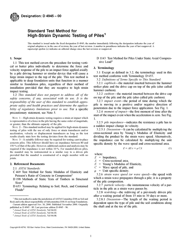
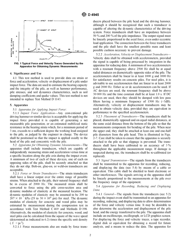
The testing equipment as define in ASTM D 4945
-
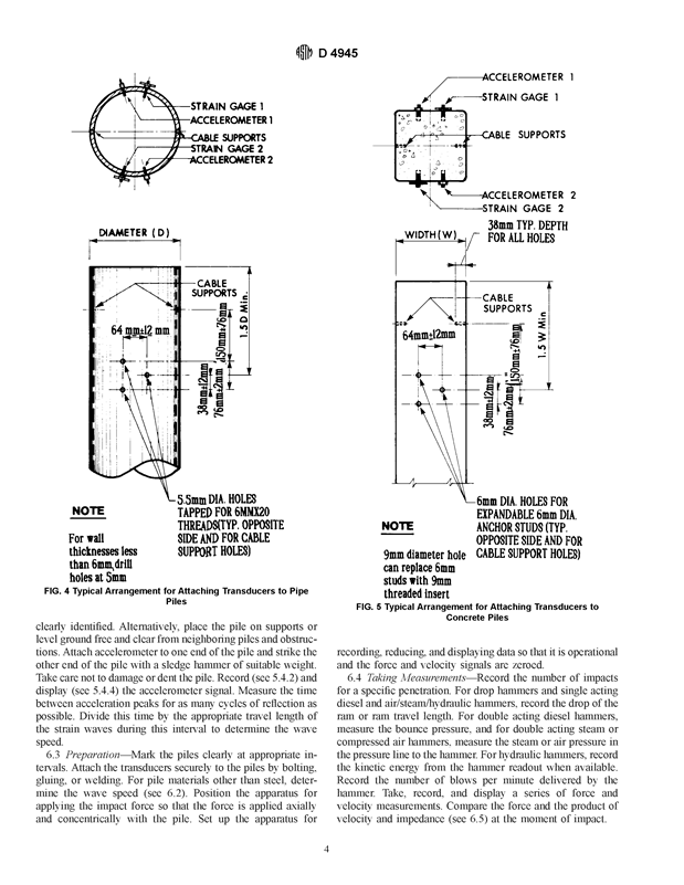
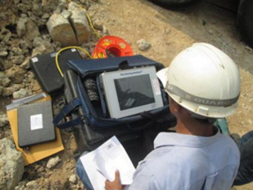
Pile Driving Analyzer model GCPC/PAK, Transducers (Accelerometer and Strain gauges) and signaling-cable.
-
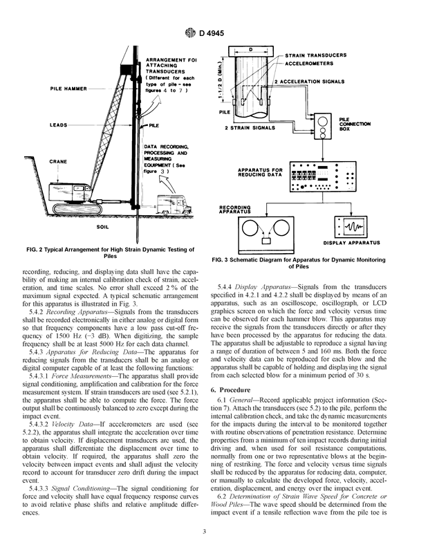
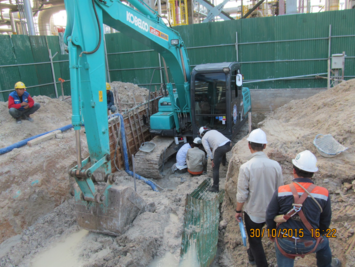
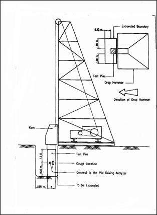
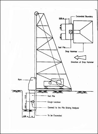
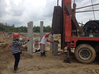
Pile driving, hammer or similar device is acceptable (see figure)
-
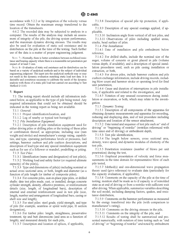
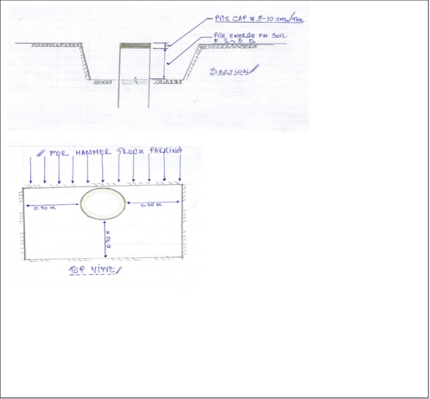
Pile cap shall prepared for bored pile to prevent any damages to the test pile
-
Pile information, size, length and age of concrete etc.
Test Procedure
-
Testing method as define in ASTM D 4945
-
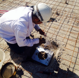
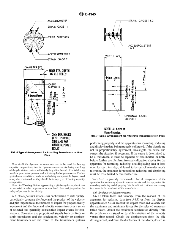
The employer shall provide access to test location. The transducers shall be place diametrically opposed and on equal radial distances at the same axial distance from the bottom of the pile. The transducers shall be attached at least one and one-half pile diameters from the pile head.
-
Hammer setting up.
The testing engineer will advise the drop height and obtain force and velocity from transducer via PDA. The test may apply several impact at various drop
-
height to generate the energy and stress wave. The transducers will captures the signals to PDA for monitoring driving resistance, pile movement, driving stress and pile integrity etc.
Subsequent analysis of the PDA data to obtain CAPWAPC.

Results and Interpretation
The results of Dynamic Load Test can be divvied as follows:
-
Case Method is the quick and powerful for field monitoring or testing results. PDA generates the results of Force (pile top force), Acceleration (A), Velocity (V) and Soil Damping (Jc) as
Re =
(1-Jc)[ F(t1)+ZV(t1)
] / 2+(1+Jc) [ F(t2)–ZV (t2)
] / 2
Where
t1 = Initail time at pile top
t2 = t1 –2L/c
Z = Pile Impedance = Mc/L
-
CAPWAPC is a numerical computer program to model the pile and soil interaction. The force and velocity records from PDA are used to determine soil resistance parameters which produces a best method between measured (Case Method) and computed pile top force and velocity
Where
Rs = Rt – Rd
Rs = Static Resistance
Rt = Total Resistance
Rd = Dynamic Resistance
The CAPWAPC would provide the following results.
-
Static Pile Capacity
-
The distribution of skin friction along the pile length
-
The end resistance of pile
-
The generated static load displacement curve
-
The extent and magnitude of any pile damage
-
Driving Stress during test.
CAPWAP : Dynamic Load test
REFERENCE
ASTM D 4945


Introduction
Dynamic Testing is a powerful tool to assess pile capacity and movement relationships, driving stress, hammer performance, pile integrity and establish a driving criteria. The test can be applied for all type of pile such as pre-cast concrete pile, bored pile, timber pile and steel pile.
Dynamic Load Test is performed by measuring stress wave and move down the pile under impact of a falling. The reflected stress wave returns to the top due to soil resistance and changing of pile properties. The pile strain and acceleration are recorded by strain gauge and accelerometer near the pile top.
Dynamic Load Test can divvied into
-
Initial Driving Test : is performed during the installation process. The testing purpose is for determine pile founding level, inspecting hammer performance, pile integrity, driving stress (compression and tension) at various drop height including pile capacity during driving.
-
Re-strike Drive Test : is performed after pile installation. The test purpose is to determine pile bearing capacity as loading requirements. The pile capacity is usually increase with time due to soil setup
in shaft friction. The soil setup period is varied according to soil property.
Testing Equipment’s
-
The testing equipment as define in ASTM D 4945
-
Pile Driving Analyzer model GCPC/PAK, Transducers (Accelerometer and Strain gauges) and signaling-cable.
-
Pile driving, hammer or similar device is acceptable (see figure)
-
Pile cap shall prepared for bored pile to prevent any damages to the test pile
-
Pile information, size, length and age of concrete etc.
Test Procedure
-
Testing method as define in ASTM D 4945
-
The employer shall provide access to test location. The transducers shall be place diametrically opposed and on equal radial distances at the same axial distance from the bottom of the pile. The transducers shall be attached at least one and one-half pile diameters from the pile head.
-
Hammer setting up.
The testing engineer will advise the drop height and obtain force and velocity from transducer via PDA. The test may apply several impact at various drop
-
height to generate the energy and stress wave. The transducers will captures the signals to PDA for monitoring driving resistance, pile movement, driving stress and pile integrity etc.
-
Subsequent analysis of the PDA data to obtain CAPWAPC.

Results and Interpretation
The results of Dynamic Load Test can be divvied as follows:
-
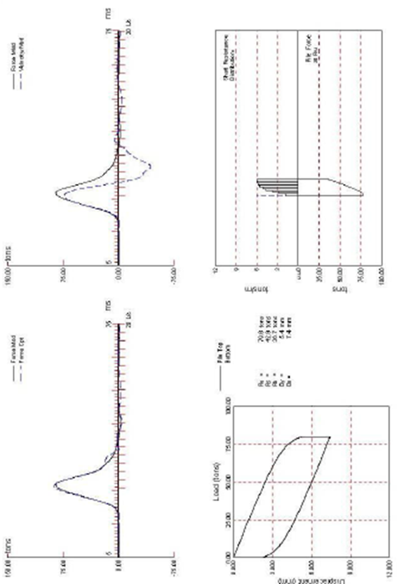
Case Method is the quick and powerful for field monitoring or testing results. PDA generates the results of Force (pile top force), Acceleration (A), Velocity (V) and Soil Damping (Jc) as
Re =
(1-Jc)[ F(t1)+ZV(t1)
] / 2+(1+Jc) [ F(t2)–ZV (t2)
] / 2
Where
t1 = Initail time at pile top
t2 = t1 –2L/c
Z = Pile Impedance = Mc/L
-
CAPWAPC is a numerical computer program to model the pile and soil interaction. The force and velocity records from PDA are used to determine soil resistance parameters which produces a best method between measured (Case Method) and computed pile top force and velocity
Where
Rs = Rt – Rd
Rs = Static Resistance
Rt = Total Resistance
Rd = Dynamic Resistance
The CAPWAPC would provide the following results.
-
Static Pile Capacity
-
The distribution of skin friction along the pile length
-
The end resistance of pile
-
The generated static load displacement curve
-
The extent and magnitude of any pile damage
-
Driving Stress during test.

CAPWAP : Dynamic Load test
REFERENCE
ASTM D 4945