หน้าแรก > งานบริการ > ทดสอบความสมบูรณ์เสาเข็ม Seismic test
การทดสอบความสมบูรณ์ของเสาเข็ม
(SEISMIC TEST TEST)
บทนำ
การทดสอบความสมบูรณ์เสาเข็ม (Seismic Integrity Test) มีจุดประสงค์เพื่อประเมินสภาพความสมบูรณ์ตลอดความยาวของ เสาเข็ม การทดสอบวิธีนี้เป็นการทดสอบที่สะดวก, รวดเร็ว, และเสียค่าใช้จ่ายต่ำ จึงเหมาะสมและเป็นที่นิยมใช้ตรวจสอบความสมบูรณ์ของเสาเข็ม ในขั้นต้น (Preliminary test) หากตรวจสอบพบสภาพบกพร่องที่เกิดขึ้น จึงกำหนดวิธีทดสอบอื่น ๆ ประกอบกับพิจารณาหรือดำเนินการซ่อมแซมแก้ไขต่อไป การทดสอบนี้สามารถดำเนินการได้ทั้งในเสาเข็มคอนกรีตอัดแรงและเสาเข็มเจาะหล่อกับที่ผลการทดสอบนี้จะระบุถึงข้อบกพร่องต่าง ๆ อาทิเช่น รอยแตกร้าว (Crack) โพรงหรือช่องว่าง (Void) รอยคอด (Size reduction) หรือบวม (Size increase) ของเสาเข็ม เป็นต้น
อุปกรณ์
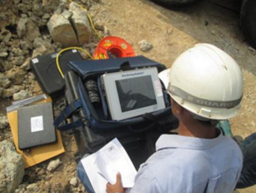
เครื่องมือทดสอบความสมบูรณ์ของเสาเข็มนั้นเป็นเครื่องมือที่ได้ รับการออกแบบมาโดยเฉพาะเพื่อการทดสอบดังกล่าว มีขนาดเล็ก, น้ำหนักเบา และมีประสิทธิภาพสูง ประกอบด้วย
-
ฆ้อนทดสอบ(Hand-Held Hammer)
-
เครื่อง Pile Integrity Tester รุ่น Collector
-
หัววัดสัญญาณคลื่นความเค้น (Accelerometer Transducer)
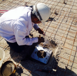
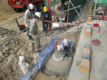
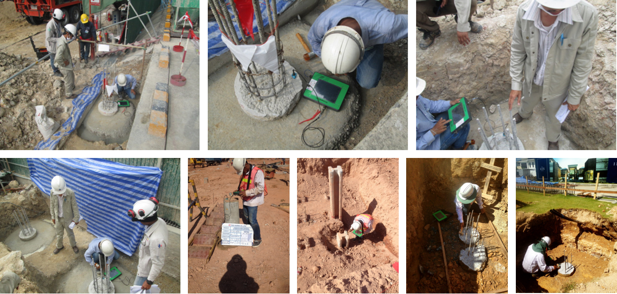
วิธีการทดสอบ
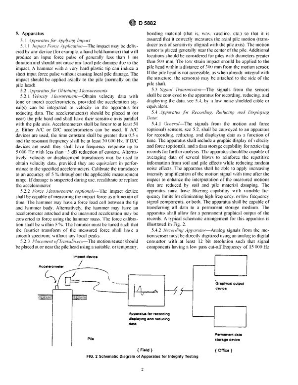
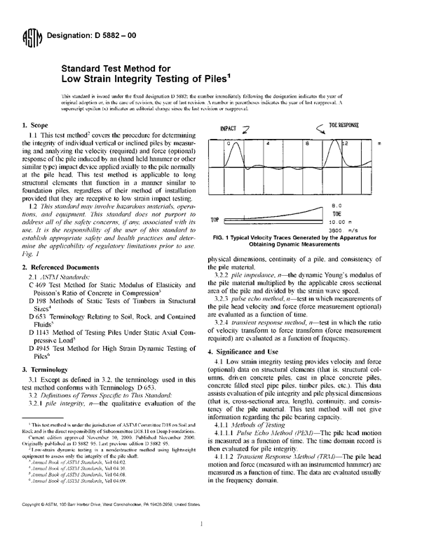
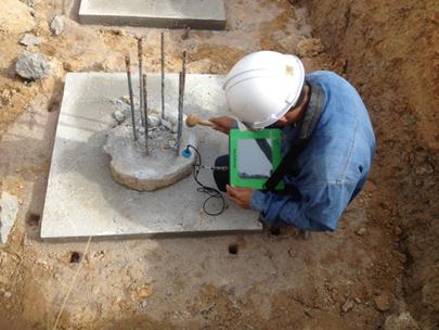
การทดสอบเริ่มจากการติดตั้งหัววัดสัญญาณคลื่นความเค้น(Accelerometer Transducer) บนหัวเสาเข็มซึ่งต้องการทดสอบโดยหัวเสาเข็มที่ดี ควรจะอยู่ในสภาพที่สะอาด ไม่มีน้ำขังหรือมีเศษดินปกคลุมอยู่ จากนั้นเคาะหัวเสาเข็มดังกล่าวด้วยฆ้อนทดสอบ (Hand-Held Hammer) คลื่นความเค้นอัด (Compression Stress wave) ที่เกิดจากการเคาะดังกล่าวจะวิ่งผ่านลงไปในตัวเสาเข็ม และจะสะท้อนกลับขึ้นมาเพื่อพบว่ามีการเปลี่ยนแปลงพื้นที่หน้าตัด หรือพบการเปลี่ยนแปลงความหนาแน่นของเนื้อคอนกรีตหรือเมื่อพบปลายเสาเข็ม คลื่นความเค้นที่สะท้อนกลับขึ้นมา ณ จุดต่าง ๆ ดังกล่าวจะถูกตรวจจับด้วยหัววัดสัญญาณข้างต้น และถูกส่งไปยังเครื่อง Pile Integrity Tester (PIT) เพื่อเปลี่ยนค่าคลื่นสัญญาณความเร่ง (Acceleration Signal) เป็นคลื่นสัญญาณความเร็ว (Velocity Signal) ก่อนแสดงผลที่หน้าจอทดสอบและบันทึกไว้ ในหน่วยความจำของเครื่องทดสอบดังกล่าว เพื่อนำไปวิเคราะห์ผลในรายละเอียดต่อไป ซึ่งลักษณะการทำงานโดยภาพรวมของการทดสอบ ดังแสดงไว้ดังรูป
การประมวลผลการทดสอบ
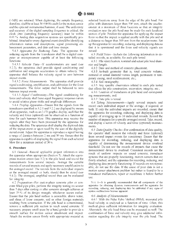
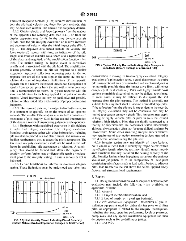
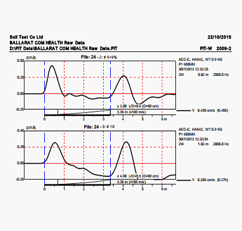
กราฟคลื่นสัญญาณระหว่างความเร็ว กับเวลา (Velocity trace) จะถูกนำมาวิเคราะห์และประเมินสภาพความสมบูรณ์ของเสาเข็ม โดยถ้าพบคลื่นสัญญาณสะท้อนกลับในรูปของคลื่นแรงดึง (Tension Wave) หรือกราฟความเร็วมีค่าเพิ่มขึ้น ณ จุดใด ๆ ตามความยาวของเสาเข็มทดสอบ แสดงว่าเสาเข็มมีขนาดพื้นที่หน้าตัด หรือค่าความหนาแน่นลดลง ณ จุดนั้น ในทำนองเดียวกันถ้าพบคลื่นแรงอัด (Compression Wave) หรือกราฟความเร็วมีค่าลดลงแสดงว่าเสาเข็มมีพื้นที่หน้าตัดเพิ่มขึ้น ถ้าไม่พบคลื่นสัญญาณสะท้อนกลับใด ๆ ที่กล่าวข้างต้น จนกระทั่งปลายเสาเข็ม แสดงว่าเสาเข็มมีสภาพสมบูรณ์ ขนาดพื้นที่หน้าตัดที่ลดลงหรือเพิ่มขึ้นดังกล่าวสามารถประเมินได้คร่าว ๆ จากค่าดัชนี แสดงความสมบูรณ์ (Integrity factor) หรือที่เรียกว่า BETA ซึ่งเป็นอัตราส่วนระหว่างค่าอิมพิแดนซ์ (Z) ของพื้นที่หน้าตัดที่พบการเปลี่ยนแปลง(Z2) เทียบกับพื้นที่หน้าตัดที่สมบูรณ์ (Z1)
Β= Z2/Z1 =A2/A1 ,(Z = EA/C)
เมื่อ
E = Elastic Modulus ของคอนกรีต
A = พื้นที่หน้าตัดเสาเข็ม
C = ค่าความเร็วคลื่นความเค้น
การประเมินค่าดัชนี ความสมบูรณ์ ของเสาเข็ม (BETA) สามารถหาได้จากโปรแกรม PIT-program
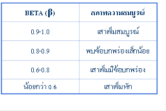
นอกจากนี้ BETA ยังเป็นดัชนีประเมินระดับความเสียหายของเสาเข็ม ( Degree of Damage ) โดยพิจารณาตามตารางข้างท้ายนี้
มาตรฐานการทดสอบ
ASTM D 5822


Introduction
Defects in concrete piles caused either during or after construction may seriously affect their performance in service.
Load testing of piles may be used to check the assumptions adopted in the load capacity design of the piles. However, it is too expensive and time consuming to use load testing as a means of checking workmanship.
Modern non-destructive methods based on small strain impulse techniques enable the integrity of all the piles on a site to be established rapidly and economically to enhance greatly confidence in the foundation.
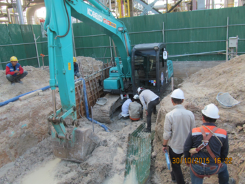
Procedure
Prior to testing the pile head should be exposed and cut back to sound concrete, with a reasonably level surface, free from standing water and pile cap reinforcing steel. It is recommended that the shaft concrete is allowed to cure for at least seven days before testing.
The test is performed by striking the pile head with either an instrumented or conventional hammer to propagate a compressive stress pulse traveling longitudinally within the pile shaft.
Analysis
As the stress pulse travels down the pile shaft, reflected waves are generated from any changes in the pile shaft acoustic impedance, which in most cases may be interpreted as changes in pile shaft area.
These reflected waves arrive some time later at the pile head and are registered by the pile head transducer. The time of arrival of these reflected waves and their form allows the elevation of the change in impedance and its sense (i.e. an increase or decrease) to be determined easily.
The test results can be analyzed in both the time domain and the frequency domain.
Time Domain
In time domain analysis (also known as the sonic echo test), pile head velocity is plotted against time.
Reflected waves generated by pile shaft anomalies are readily identifiable with this method of presentation of the test results.
It is also possible to compensate analytically for the stress pulse by the soil resistance supporting the pile shaft.
Frequency Domain
Frequency domain analysis may also be performed. This involves converting the time domain signals via. Fourier analysis into frequency spectra. If the information obtained from the instrumented hammer is included in the analysis a small strain pile dynamic stiffness value for the pile can be calculated.
This is a very valuable index parameter, particularly useful in determining defects in the upper two to three diameters of pile shaft, which is often a critical region.
Interpretation
Adoption of test results analysis in both the time and frequency domains maximize the reliability of the test interpretation.
In addition to the vibrational response of the pile head during the test, information regarding the pile dimensions, concrete mix design, reinforcing steel details and the soil conditions are desirable to complete the interpretation of any test results.
Preliminary identification of anomalous piles is easily accomplished on site.
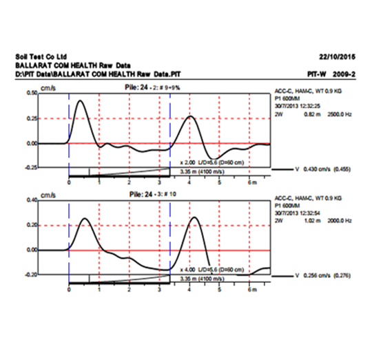
This display shows a typical time domain test result
REFERENCE
ASTM D 5822